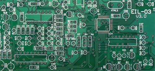

This is the fundamental PCB circuitry.Ī layer of soldermask is added to both sides. Now the coating is removed, exposing all the traces and component pads, vias, etc. The chemical will only remove the copper and not the copper protected by the coating. It is now time to remove all the copper chemically. The photo-resist is stripped (chemically), from the board. The next step is the deposit a coating over the exposed copper, this coating protects the copper on vias, component holes and traces from being removed during the etching stage. The unexposed areas of resist are removed by passing the boards through a developer solution leaving the copper track\pad pattern visible on the board. The copper film is placed over the board, aligned with the drills and the board is exposed to UV light. This is a soft, photo-sensitive material. This process, known as electroplating, is repeated until the copper thickness reached is optimum for connectivity, typically 25um. As the walls are non-conductive, a layer of copper is deposited chemically over the hole walls. The hole walls need to layered with copper. This is the drill file containing the information used to drill the necessary holes.Īt this point there is no electrical connection between the layers. In the PCB design stage, using the DesignSpark software, a drill or DRL file is created. To create multilayered PCBs combinations of the pre-made material are pressed together with other layers or non-copper clad FR4 (Prepreg) used to isolate the copper layers from each other. The FR4 material is fibreglass and gives the board its rigidity. This is generally bought pre-prepared from suppliers. The double sided PCB is made of epoxy glass (FR4) with copper foil on both sides of the epoxy glass. The NcDrill file defines the location and size of each hole on the PCB both PTH (pin through hole) and NPTH (non pin through hole). Each Gerber file represents a component necessary for PCB Manufacture including the copper layers, soldermask and silkscreen data, the PCB outline and the solder paste data for producing a laser stencil for assembly.
#What is pcb software
Using DesignSpark PCB Software to design your PCB, Gerber and NcDrill files are created. To describe how a PCB is created, we’ve taken a standard 2 Layer or Double Sided PCB. They have interconnecting layers that allow the overall size to be reduced – think of mobile phones in the 80s versus the smart phones of today. PCBs have moved from 1 layer boards to the 20 + layer boards found in your smartphone. He developed and patented a number of applications that eventually grabbed the attention of US military. Paul Eisler, an Austrian refugee to Britain in 1936, is considered the real founder of the PCB. The Printed Circuit Board was born, opening the door to smaller, simpler and less cumbersome designs. In 1925, Charles Dukas of the US, created and patented a way of electroplating an electrical path onto an insulated surface. It is the basic building block of any electronic design and has developed over the years into a very sophisticated component. This does not apply to backplanes assembled backplanes are called backplane assemblies by the IPC.A Printed Circuit Board or PCB is essentially a board that connects electronic components. The IPC preferred term for populated boards is CCA, circuit card assembly. In informal use the term “PCB” is used both for bare and assembled boards, the context clarifying the meaning. Today printed wiring (circuit) boards are used in virtually all but the simplest commercially produced electronic devices, and allow fully automated assembly processes that were not possible or practical in earlier era tag type circuit assembly processes.Ī PCB populated with electronic components is called a printed circuit assembly (PCA), printed circuit board assembly or PCB Assembly (PCBA). Use of the term PWB or printed wiring board although more accurate and distinct from what would be known as a true printed circuit board, has generally fallen by the wayside for many people as the distinction between circuit and wiring has become blurred. W hen the board has only copper tracks and features, and no circuit elements such as capacitors, resistors or active devices have been manufactured into the actual substrate of the board, it is more correctly referred to as printed wiring board (PWB) or etched wiring board. PCB or Printed Circuit Board is the traditional name for the bare board of which you supply us with the layout data and which you use to mount your components on once we have delivered it to you.Ī printed circuit board, or PCB, is used to mechanically support and electrically connect electronic components using conductive pathways, tracks or signal traces etched from copper sheets laminated onto a non-conductive substrate.


 0 kommentar(er)
